To explain the various structures that can occur in cast iron, the iron-carbon double diagram was introduced as far back as 1904 [1]. Cooling curves showed that the formation of cementite was always associated with a lower eutectic temperature as compared to the formation of graphite that took place at temperatures about 100 C higher.
Although in daily foundry practice the tendency of a cast iron to solidify according to either one of the systems is usually treated as a matter of available nuclei, there appears to exist many different views as to the actual chilling tendency. Fras [2] mentions at least six different mechanisms. The proposal of the Dendrite Growth Theory, which claims that a dendritic growth morphology of the austenite phase determines the final graphite shape, lead to the thought that the carbide phase in cast iron might also be influenced by the austenite growth.
Structure of the cementite-eutectic.
Two types of cementite eutectic exist. The original eutectic -Ledeburite- in which small islands of austenite are dispersed in the carbide phase, and the plately, divorced or massive carbide eutectic. Typical of the last is the fact that the second eutectic phase, the austenite is lacking. To account for this, it is assumed that the accompanying eutectic austenite settles on the existing primary austenite.
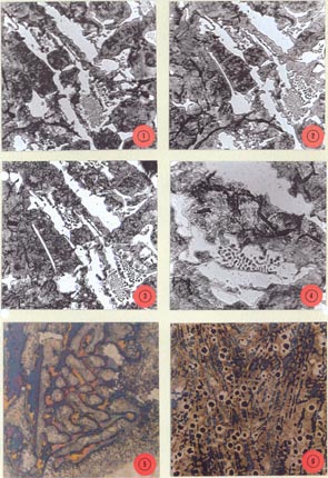
To gain more insight in the three-dimensional structure of the eutectic, some successive grindings were applied on a mottled region in gray iron. Four of these microstructures, taken at the same spot, are represented by photographs 1 to 4. These photographs show ledeburitic, massive and needle shaped carbides. From these photographs it can be deduced that the needle-shaped carbide actually forms a continuation of a massive carbide. The successive grindings surprisingly show that the austenite islands within the ledeburite are in fact sections through small compact dendrite arms that belong to the neighbouring austenite. That means that they do not form the second phase of a eutectic at all. The same condition is shown in photo 5, where the austenite islands are an integral part of the adjacent austenite.
In all cases, the carbide 'eutectic' consists of only one phase! This phase takes the space that is left over by the primary austenite as is shown by photo 6. Not a single indication exists that a second austenite phase, which makes out 50 % of the eutectic, really forms, let alone that it crystallizes directly on the primary phase.
The hypereutectic carbide region.
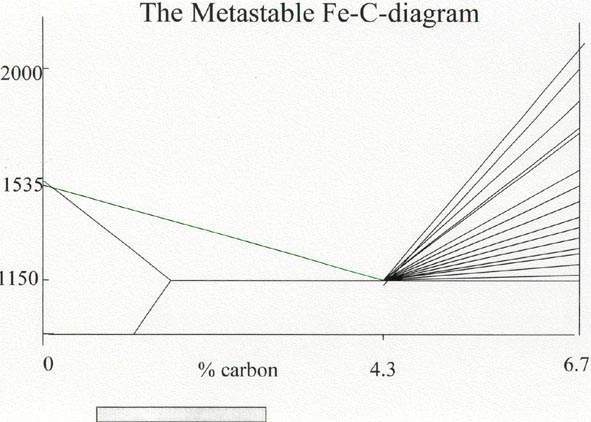
Usually, foundrymen do not have to deal with this range of cast iron structures, thus relatively little attention has been given to this region. Moreover, research in this high carbon range has posed many practical problems in the past, f.i: -Only extremely rapid cooling gave rise to the formation of primary cementite -Primary carbides in unalloyed cast iron can only be found at carbon contents of max 6%. -Huge differences in melting temperature of primary cementite are mentioned ranging from 2000 [3] to 11500 C.[4], nowadays, only theoretical values are used.Next figure shows in a symplified way the range of liquidus lines that have been claimed since 1900.
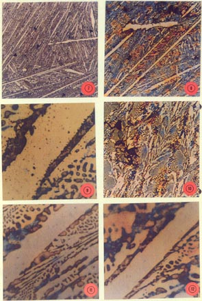
To study hypereutectic carbide structures, use was made of a high manganese containing pig iron. Analysis: C 4.68 %, Mn 7.50%, Si 1.04 %. Structures that can be found in this material are presented by the photos 7-12. Photos 7 and 8 show large primary carbide needles, along with some massive carbides as well as a ledeburitic structure lying between the carbide needles. This ledeburite is laid down in a dendritic structure (photo 10).
If one examines the primary structure at a higher magnification however, it appears that there exists also an austenite needle-shaped phase in the structure, as shown by photo 9. In fact this is the only real needle shape within the structure! As soon as the austenite needle is interrupted, the carbide phase just follows the contours of the austenite needle and becomes indistinguishable from the ledeburitic carbide phase.The appearance of needle shaped primary carbides is thus an optical illusion, caused by the delineating effect of the surrounding austenite dendrite needles. This is clearly shown in photos 11 and 12, where the carbide phase fills up the space left over by the austenite.
Exactly as was the case in the ledeburite structure, the primary carbide phase is just a space filling component, indicating that it was the last phase to solidify into a final shape forced upon by the austenite. Olen and Heine [4] did suggest 30 years ago that carbides might best be regarded as ordered solid solutions rather than as separate entities which precipitate directly from the liquid. As no low-carbon component crystallizes at the same time to raise the carbon content of the remaining liquid and no other carbon source is available, it must be concluded that locally, the solubility of carbon in the remaining-melt can increase up to the composition of iron-carbide, t.i. 6.7% !
Simple as this observation may seem, accepting these statements has a wide bearing, because it not only means that the existing iron-carbon double diagram is in error, but that its concept is fundamentally wrong!
References:
[1] E.Heyn, Labile und metastabile Gleichgewichte in Eisen-Kohlenstoff-Legierungen, Zeitschrift für Elektrochemie, Vol.10 (1904), pp.491-503.
[2] E.Fras, H.F.Lopez, A Generalized Theory of the Chilling Tendency of Cast Iron, AFS Transactions, Vol.101 (1993), pp.355-63.
[3] H.Hanemann, Kohlenstoffgehalte und Gefügeerscheinungen hochgekohlter Eisen-Kohlenstoff-Legierungen. Stahl und Eisen, Vol.31 (1911), pp. 333-36.
[4] K.R.Olen,R.W.Heine, A Revision of the Fe-C-Si System. AFS Cast Metals Research Journal, Vol.4 (1968), pp. 28-43.
Captions to Appendix A:
Photos 1.- 4 Carbidic region in low-Cr/Mo alloyed Gray Iron. Successive grindings on same spot. Showing that the eutectic austenite actually is part of the neighbouring primary austenite. V=200x., Nital.
Photo 5. Ledeburitic region in Nodular cast iron. Showing that the eutectic austenite actually is part of the neighbouring primary austenite. V=1000x., Primary etched.
Photo 6. Carbide formation in thin-walled nodular iron. Carbide shape is determined by growth of austenite. V=50x., Primary etched.
Photo 7. Primary carbide needles in high Manganese pig iron.V=50x, Nital.
Photo 8. Primary carbide needles in high Manganese pig iron. V=50x, primary etched.
Photo 9. Austenite needle in the same specimen. V=500x, primary etched.
Photo 10.Ledeburite in a dendritic macro-structure in same specimen. V=100x, primary etched.
Photo 11.and 12 Carbide phase is continuous in whole structure. Delineating effect of austenite needles pretend the presence of carbide needles.